Scaffolding parts name
Base plate
Scaffolding parts name Tubes and fittings are to comply with relevant standards, ends cut clean
and square, free from bends, distortion, corrosion, splits or surface flaws.
Fittings free from worn threads or damaged bolts and excess oil which may reduce friction grip.
Boards to comply with relevant standards; not to be warped, twisted, split or badly worn, or painted to conceal defects.
Foundations-Scaffolding parts name
Foundations should be of adequate strength to support and distribute the load. On all other surfaces, the load should be spread by using base plates and sole plates. The soil or ground beneath the sole plates should be level and properly compacted.
A sole plate used on hard ground, beneath any one standard, should be at least 1000cm5 with a minimum dimension of 219mm. If a timber sole plate is used it should not be less than 35mm thick.
At all times a metal base plate should be used between soleplate and standard. On sloping ground, steps should be cut into the slope to accommodate
sole boards and base plates. If the slope exceeds 1:10, an engineer should check that the ground has sufficient stability.
Standards-Scaffolding parts name
These will be placed vertically to within +/- 20mm in any 2m in length, to
a maximum total deviation of 50mm.
Joint pins may be used to connect standards in line when the joint is in
compression – where the joint is in tension then sleeve couplers should
be used.
Joints in standards should be staggered such that adjacent standards
are not jointed in the same lift. Of the 4 standards at the corner of the
scaffold, only 3 may be joined in the same lift, except in the lower 6.5m
of the scaffold where an extended base lift is necessary. In such cases all 4
standards may be joined in the same bay, provided one of the joints is
lapped with tube and parallel couplers.
Ledgers-Scaffolding parts name
Ledgers are fixed to standards with right angle couplers. They would
normally be horizontal but may follow the slope of ground at the “foot”
lift. In this case, the ledgers would be fixed to the transoms which are
attached to the standards with right angle couplers.
Joints in ledgers should also be staggered, i.e joints in adjacent ledgers
should not occur in the same bay. These joints should be made with
sleeve couplers and not be more than one-third distance away from a
Standard – Scaffolding parts name
Joints in ledgers on the same lift and in adjacent lifts should not occur in the same bay unless there is unjointed guardrail (not to be removed) when joints in the ledgers above and below can be in the same bay.
The spacing of ledgers (lift heights) will be:
independent tied scaffolds – 2.0m
putlog scaffolds – 1.35m
First lifts of up to 2.7m are acceptable where access underneath the
the scaffold is required, this will result in reduced loading capacity.
Transoms
Transoms are secured to ledgers with either right angle or putlog couplers unless braces are secured to them, in which case only right-angle couplers are acceptable. On boarded lifts, transoms will be spaced to ensure adequate supporting of the scaffold boards overlap 50mm over the transom. On non-boarded lifts and transoms should be secured at not more than 300mm from each standard or pair of standards.
Couplers – Scaffolding parts name
These components are classified into two categories – load-bearing and
non-load bearing.
Load bearing couplers or components are:
- Right angle couplers
- Swivel couplers
- 5 KN brace couplers
- Adjustable fork heads
- Adjustable base plate jack
Non-load bearing couplers or components are:
- Expanding joint pins
- Toeboard clips
Bracing
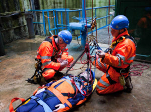
No scaffold can remain stable or safe unless properly braced. Bracing should remain in position at all times to ensure this stability. There are two main types of bracing, as follows: What are fall protection systems for scaffolders
Façade Bracing
Fixed to the long face of the scaffold normally parallel to the face of the structure and is fitted to the outside row of standards. It can either run across the face of the scaffold to its full height at an angle of 45° or run in a zig-zag fashion to its full height. How to calculate scaffolding load
Bracing should be provided at least every 3.0m along the scaffold. Bracing will be fixed to extended transoms with right angle couplers or to standards with swivel couplers. Where braces are fastened to transoms, the transoms should be fixed with right-angle couplers, (load-bearing) to the scaffold. Brace couplers may be used as an alternative. Working at height safety
Joints in any continuous sloping tube can be made in one of three ways:
Overlapping the two lengths of the tube by at least 300mm and fixing with two parallel couplers. A joint pin with a splice tube fixed with parallel couplers either side of the joint. A sleeve coupler.
Ledger Bracing
Fixed to join inner and outer alternate pairs of standards, fixing is by using right angle or brace couplers connected to the ledger or with swivel couplers to standards. Working at heights procedure When a bay length is 1.5m or less, the bracing may be fixed to every third pair of standards. On boarded lifts, the brace would be fixed under the outside ledger to the inside ledger of the lift below to avoid the toe board. Bracing may be fixed from the inside ledger to the guardrail level of the below provided that every pair of standards are braced. Scaffolding safety checklist
Click Here to Subscribe our Youtube Channel for free HSE Training Videos
Click Here to like & receive our Latest Posts on Facebook
Share on: